PCB Business Cards
Brief
Every engineer graduates, sends out a stack of CVs, gets nowhere, then decides to build a PCB business card because we got into this to build, not write.
Initial Hardware Decisions
I based my card heavily on Dennis Kaandorp's PCB Business Card.
There were plenty of attractive features in Dennis' design that I wanted to carry over in my design:
- Simple button cell power source
- Plays an instantly recognisable game (snake)
- Uses an Arduino compatible microcontroller
Despite these clear benefits, there was a much bigger factor to me choosing to base my design off Dennis' design; I could understand what the hell was going on in his schematic.
However, I chose to make some changes:
- No charlieplexing
- Slightly larger LED matrix
- Extra button
The extra hardware required more pins than the ATTiny 1616 Dennis used in his card. I simply added 1 and used the ATTiny 1617. Since this was my first real PCB project I chose to keep it simple.
Since I intended these cards to lead me to making money, I did all the PCB design with my only remaining option - KiCad. I had a whole 3 hours of experience with KiCad from one uni lab so naturally this was a good excuse to actually learn how to use the damn thing.
Being business cards and all they also had to include my name and a QR code that goes somewhere useful.
V1: Doing it Wrong
The first round of designing came with no attention to aesthetics, readability or debugging. Of course the V1 design was plagued with mistakes that would have been easy to avoid had I focused on the second two points. But then it wouldn't be a V1 now, would it?
PCB
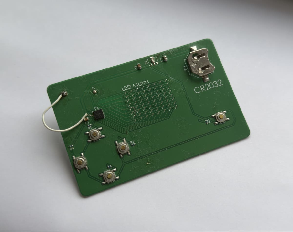
This image is the first card I assembled to test that the MCU was working, however, it is not the card where I soldered the LEDs for the purpose of testing those. So uh ignore what I say about soldering LEDs for now. This project has been on and off for over six months and that has caused some problems with documenting everything.
The keen-eyed readers might notice the big fat botch wire going to the MCU. I didn't pay close enough attention to my ground pour and ended up failing to catch the fact that the MCU was not grounded. Oops. At least the successful botch wire is somewhat a flex (cope).
To keep this one nice and cheap, I ordered 5 PCBs to be manufactured by JLCPCB and chose to hand solder the components myself. Most of the SMD parts were bearable but the LEDs drove me insane. You can probably tell since I barely soldered a quarter of them. The worst part is the fact that they are polarised. It got to the point where it was easier to just grab another LED from the reel if I lost track of the polarity.
I had always intended to power the cards off a CR2032 battery. Dennis used a custom footprint for his card that integrated the battery holder into the PCB itself. I didn't want to touch custom footprints so I just chose one of the built in KiCad footprints that I liked the look of. To nobody's surprise this didn't work right and the battery holder I chose is far too small for a CR2032. Looks even more embarrassing with the proud CR2032 silkscreen label.
The issues with the power supply didn't stop there, and the linear regulator I chose in a similar fashion also didn't work. I forget the exact model I ended up going with initially but it required a higher input voltage than my battery would provide. This didn't really end up mattering too much as this version spent its whole life wired directly to a programmer with its own clean voltage source.
Finally I needed a header to program the MCU. Like the rest of this design I chose a footprint I liked the look of and hooked it right up to the UPDI pin on the MCU. While this did work, it was awkward to use. Like the power supply issues this was less of a problem because this card was wired right up to a programmer, however it would be much harder to quickly flash a set of cards with this setup.
Here is a list of most of the issues with the V1 in order of severity:
- MCU is not grounded
- Linear regulator does not work for this application
- Battery holder is the wrong size
- Lame programming header
- I removed some of the silkscreen component markings but not all of them (who does that?)
- The routing in general just looks sloppy
Despite this long list of issues the buttons, LED matrix and MCU (minus grounding) all worked properly on the first go.
V2: Doing it Right(er)
With all the lessons from V1 learned, it was time to work on the V2 design with a big push on aesthetics. I need to be able to hand this thing out to people.
Schematic
The schematic didn't really change much between the versions. I added some more testpads for debugging and fixed up the footprint issues. Eventually I cleaned up the schematic when someone asked me for a copy and I realised what's good enough for me isn't good enough for everyone.

PCB
Having built up my confidence with KiCad designing the V1 board, I was able to focus much harder on the PCB design. I think the biggest issue I faced with the first iteration is a lack of intuition with the PCB footprints. For some reason I chose different-sized capacitors for the three different caps. It feels like such a silly thing to do now but when I was just getting started all I was thinking about was getting it working.
My improved confidence with KiCad really let me slow down and be more intentional with my component and trace placement. The buttons are now arranged symmetrically, the gaps between components are even, and traces are more neatly routed.
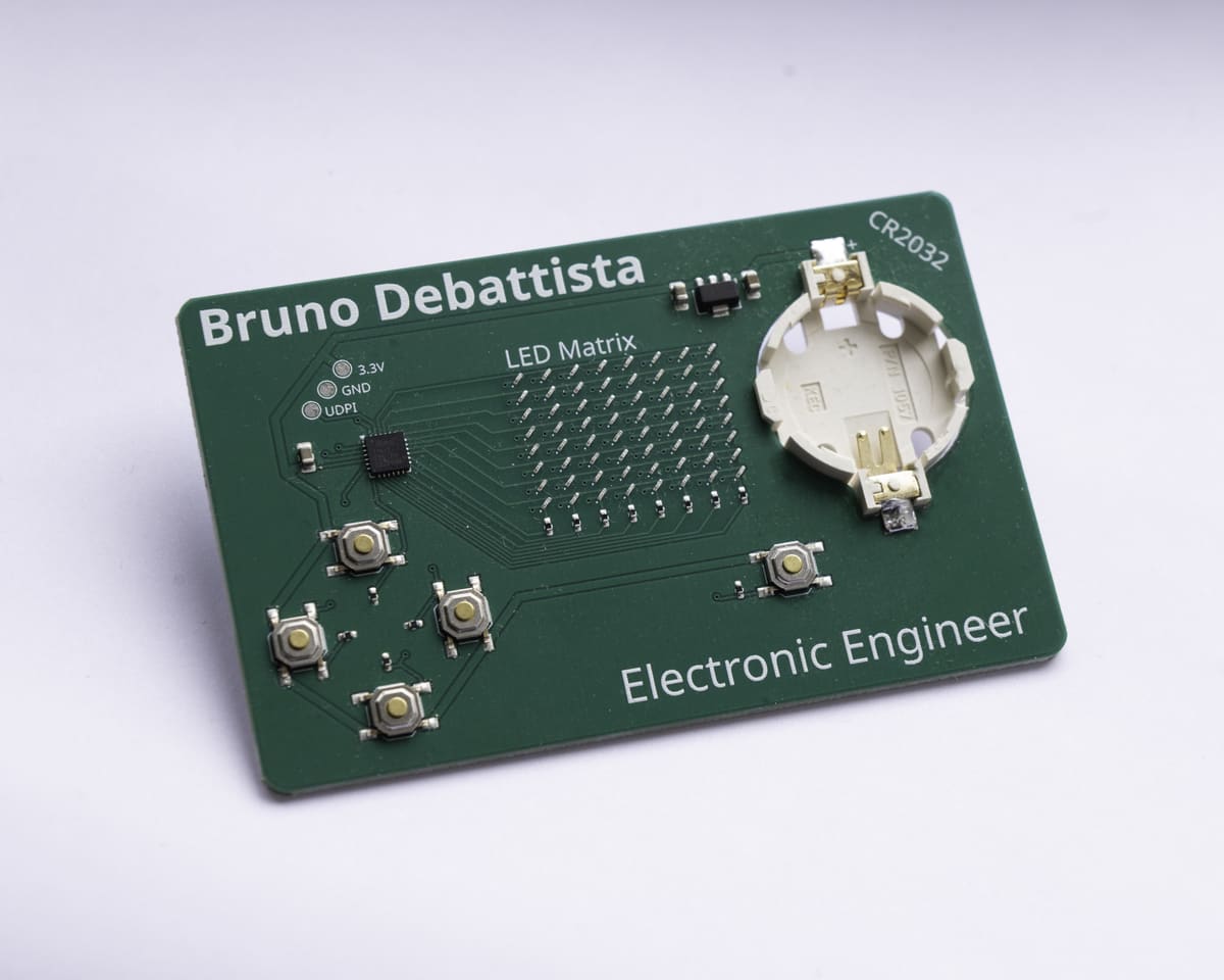
Fun with Silkscreen
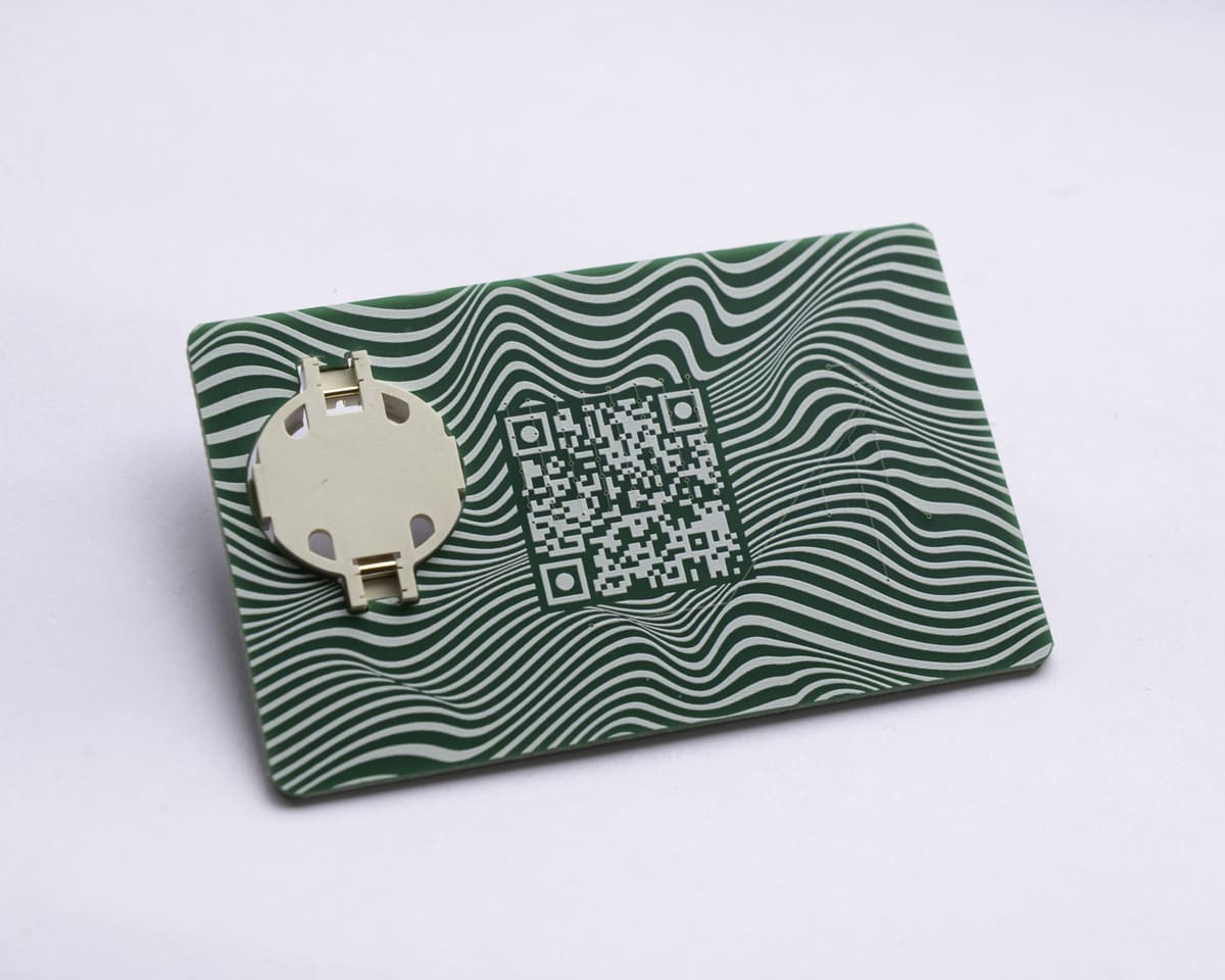
Silkscreen is free and should be used as such. With a stronger focus on aesthetics I chose to put my name on the front of the card since that's what the user is always looking at. The QR code went on the back with a funky pattern around it. I put the whole design together with the greatest graphic design program in the world: PowerPoint.
Unfortunately the elite website you are reading this story on did not exist when I started this project so the QR code takes you to my LinkedIn which is pretty outdated (and unsexy). This is one of those little things that shows up on the first go, and will never occur on another PCB I make. I suppose an excuse to clean that up isn't so bad.
Assembly
The PTSD induced from hand soldering 0603 LEDs forced me to accept the fact that I should have JLCPCB manufacture and assemble the boards for me. While PCB assembly certainly made this project easier, PCB assembly significantly increased the price per unit of the cards. I need a job to make the cards but I need the cards to get a job. Eventually the cycle broke and I landed a non technical role and spent a nice chunk of my first paycheck on 15 fully assembled cards. All I had to do was add my battery holder as JLCPCB did not have it in stock.
Assembly Costs
PCB manufacturing, assembly, shipping and taxes all added to $205.96 which gives a unit price of $13.73 per card or roughly £10 per card. Not terrible for something I'm giving away but still not an insignificant cost.
Mystery LED Issues
Having JLCPCB do all the board assembly for me gave me some very clean looking boards but there seems to be two different issues with the LED matrix.
Firstly the top row of LEDs does not work on any of the boards. I have no idea what is going on here as all the traces and solder look fine. The LEDs themselves work fine as I can get them to light up individually with a multimeter. I did change the spacing of the LEDs between the two PCB versions but I assume a mistake in the PCB routing would have taken out the whole matrix. The fact that the exact same issue is present on all of the boards suggests some routine issue and not just some random error but I can't tell what.
The other issue is that some of the LEDs in the working part of the matrix don't work. Most boards have at least one LED that doesn't work. Unlike the top row issue this problem is randomly distributed throughout the boards. Again I know the LEDs themselves are working. Perhaps the pick and place machine didn't quite put the LEDs down in the right place. Another theory is that this stemmed from the fact that I left the hand solder LED footprints on the board. At some point I will have to try reflow some of these LEDs to see if the issue is just a cold solder joint.
Never Perfect Just Good Enough
No project is ever perfect, it just gets closer and closer to good enough. The V2 card is a vast improvement over the V1 and is at a stage where I am happy to show it off, however it has its own issues:
- As mentioned not all the LEDs work. This may be fixable
- The battery holder looks cool but it clearly wasn't designed for frequent battery removals making it awkward to remove the battery
- The UPDI pad is labelled as UDPI. I only noticed this super late as "UDPI" just sounds better to me. Maybe I should take that one up with Atmel
Despite these issues the cards are comfortably in the "good enough" territory and at this point I would rather do a whole redesign from scratch with the fundamental flaws of this project addressed rather than try go for a V3
Firmware
The sad truth that many hardware guys struggle with is the fact that if you're using a microcontroller (you probably are in current year), then your sexy hardware won't do squat without some code.
Coding has always been a strange elusive skill for me. I have understood the fundamental concepts for years now, but I have always struggled to turn that knowledge into useful, interesting projects. I've always wanted to be good at coding but found the journey to getting there uninteresting so I never pursued it.
Thankfully, we figured out that if you throw a bunch of compute at your problems, you can finally get good results with AI. I was very skeptical of AI for quite a while. The tech was undeniably quite impressive, but I had yet to find a real use for it for what I do. A wise friend of mine said he was impressed with Claude's capabilities and suggested I give it a go. Several months had passed since I got the new cards, and this was the perfect boost to get me looking at this project again.
This is what actually got me to clean up the project's schematic so I could give Claude a schematic it had a better chance of reading. All I had to do to get started was give Claude the schematic, explain the project and let it get started. While it did a fantastic job getting me what I wanted, it was not a silver bullet, and I intentionally had it start with code to drive the LED matrix, then handle the button inputs. I didn't want to give it too much in one go because I knew I stood no chance debugging its code.
I insisted on having Claude generate me the code in stages for my own learning too. By having to put Claude's code together, it helped me get more familiar with C than any Hello World tutorial ever did. I began to really enjoy the process of "writing" the code for this as I could come up with cool features within the power of the device and see these changes happen at a rate I couldn't ever achieve myself.
I did all of the firmware development for this project using Claude's free plan, and ironically, the brutal usage limits really stopped me from locking in way too hard and forgetting to sleep. Unintentionally ended up helping me pace myself and not get burned out.
EEPROM & High Scores
As the project began to mature, I knew it would be a no-brainer to add a persistent high score feature to the cards. They don't stay turned on for long, and I always pull the battery out when I'm done showing one off as there is no sleep feature implemented. Since the ATTiny 1617 features EEPROM storage on the chip, this was the obvious place to put the high score. The function for writing the update uses the eeprom_update_byte function to avoid wearing the EEPROM out with unnecessary writes.
I always knew this chapter was going to be strange to write because coding really never clicked with me. While I don't think AI is going to replace real developers, it is very nice to have an option for the hardware apes who need to be able to grab something to understand it.
Result
I started this project at a time when I was feeling exhausted with trying to pursue a career in electronics. While this project taught me a great deal and provided me with some damn cool hardware to show off, the best outcome of this project was being reminded that I really do enjoy my subject. And that's a feeling no amount of money or job can give you.